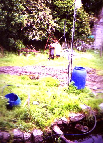
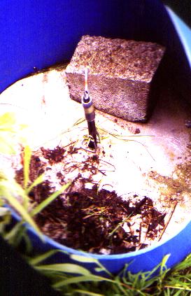
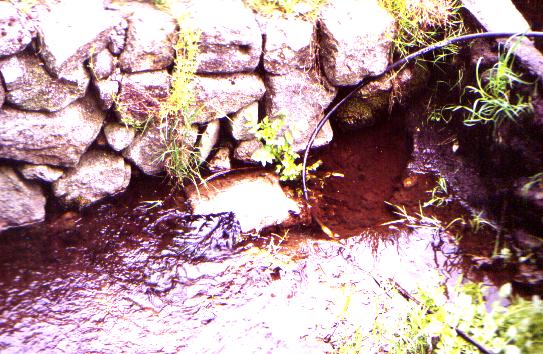
Here is the whole thing. The cut blue barrel is directly over where
the hole was. (The pipe in the foreground is not part of the system). Neither
are the assembled equipment in the background or the blue barrel beside
the up pipe.
Here is the sieve at the water intake
Not the best resolution I'm afraid! It is just a plastic can with large
holes cut in the sides and the top and with wire mesh attached.
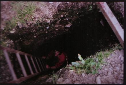
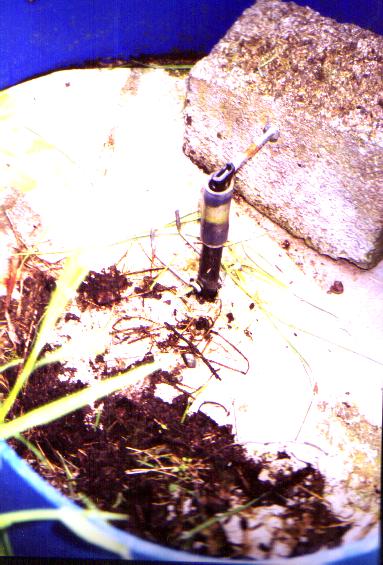
These are pictures of the entry to the vertical down pipe.
Here it is with the top on.
The top prevents dirt falling in, allows you to stop the flow
of water, and allows you to adjust the flow of air into the pump.
I made the air intake adjuster separately and added it with the clear
plastic pipe as the joiner. The half block is there just to hold down the
aluminium top.
This is the top unassembled
Here is the water going down the pipe with the lid off. Air gets
sucked down too. The top makes it more effective. The water enters through
a pipe on the right of the picture.
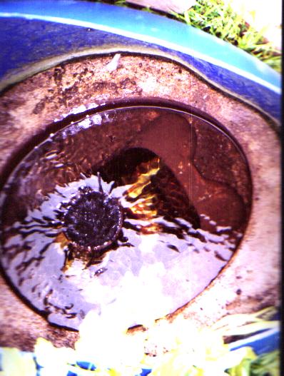
This is the water exiting, it is swirling a bit but about 30% of its
energy has been used to pump air and more has been used up in the swirling
that took place as the air descended. This was one of the first pulser
pumps that I made and I didn't make the bottom chamber long enough. Consequently,
when
it runs fast, some air goes through with the exit water. You can see some
bubbles . The plastic can protects the exit pipe from debris or sand falling
back down it.
You can ignore the black pipe in the picture. It is not part of the
system
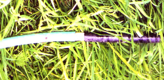
Below is a picture of a very important piece of the system (for
when you are making a split process pump). The pipe, between the green
and the black pipes, contains a bead with the thread hole drilled to a
larger size. Air is sometimes sucked into the system is pulses, and the
bead evens out these pulses to give a more even delivery to the end user.
The improvement in water pumping when you include this bead can be
more than 10% so it is well worth it!
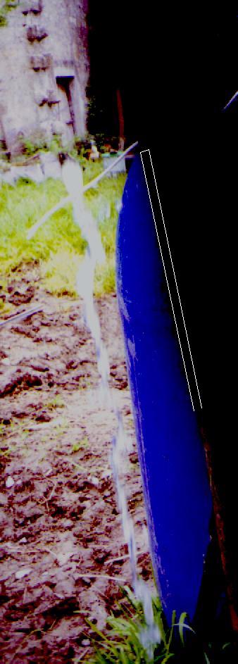
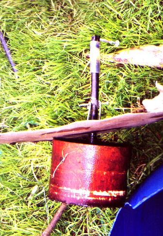
Here is a photo of the water being pulsed out of the pipe at about
1.2 meter high and going at about 8 litres per minute. (this is not the
best height to pump). In the first picture, this is just above the blue
barrel and normally it pumps up into the chamber high above the barrel.
Perhaps I was too close for the camera and the top section ot the pipe
didn't come out right but the falling water did. The bottom of the
pipe can be seen as a red tinted piece in the bottom right of the picture.
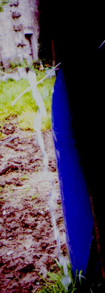
Here it is with the pipe outline marked in and a pulse
has just left the pipe.